
Struggling to define the right precision for your new plastic part? A mistake here can lead to poor fits, assembly failures, and expensive mold rework, delaying your entire project.
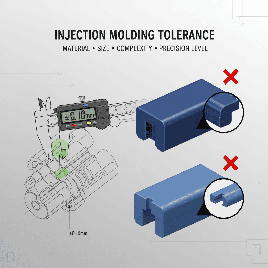
There is no single, fixed standard tolerance for injection molding1. It is a dynamic value that depends on the specific plastic material, the size and complexity of the part, and the required level of precision. General commercial tolerances2 often start around ±0.1mm but can vary significantly.

This might sound complicated, but it's actually a good thing. It means we don't use a one-size-fits-all approach that might compromise your product's quality or inflate its cost. In my 15 years in this industry, I've seen that the path to a perfect part is through understanding these variables. It’s about a detailed conversation, not just picking a number from a generic chart. Let's break down how we determine the right tolerance for your specific project.
How do different plastic material3s affect tolerances?
Thinking all plastics behave the same during molding? This is a common oversight that can lead to unexpected dimensional issues. The material you choose is the foundation of your part's final precision.
Different plastics have unique shrinkage rates4 and thermal stability. High-precision materials like ABS and PC hold tighter tolerances, while more flexible materials like PE have a wider acceptable range. The material choice is the first critical decision in defining achievable precision for your part.
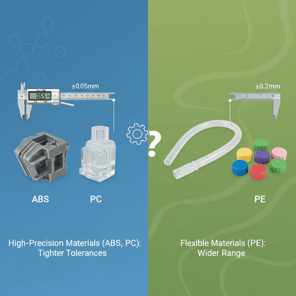
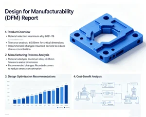
I often work with clients, from automotive suppliers to electronics developers, who have a specific performance in mind for their product. The first thing we discuss is the material. A client developing a rugged housing for an electronic device needs something strong and stable, like PC or ABS. These materials are fantastic because they are rigid and have very predictable, low shrinkage rates after molding. This allows us, as the manufacturer, to control dimensions very tightly. For a small part made of ABS, we can often achieve precision tolerances as fine as ±0.05mm.
On the other hand, another client developing packaging might choose a material like Polyethylene (PE) for its flexibility and cost-effectiveness. However, PE has a higher and less predictable shrinkage rate. This means we have to plan for a wider tolerance range5. It's not a flaw in the material; it's simply its nature. Trying to force a PE part to hold a ±0.05mm tolerance would be impractical and lead to a high rejection rate. Instead, we work with a tolerance that is appropriate for the material, ensuring consistent production and a functional final product.
How are standard tolerances actually calculated?
Are you looking for a simple chart to find your tolerance? While helpful, these charts require context. The size of your part plays a huge role in what level of precision is realistic.
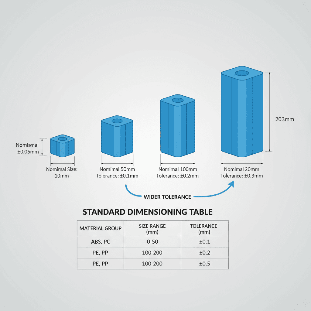
Tolerances are often calculated using standard dimensioning tables6 that group plastics by their molding characteristics. These tables provide specific tolerance values based on the part's nominal size7. As the size of the feature increases, the achievable tolerance range naturally becomes wider.
When we get a new project, we don't just guess the tolerances. We often refer to established industry guidelines that categorize plastics into groups based on their molding behavior. This gives us a solid, data-driven starting point for our conversation with you. For instance, a high-precision material like polycarbonate (PC) would be in a top-tier group.
Let's look at how this works in practice. The key principle is that it's much easier to hold a tight tolerance on a small feature than on a large one. Material shrinkage, cooling variations, and internal stresses have a greater effect over larger distances.
Example Tolerance Table (Group 1 Materials - e.g., PC, ABS)
Here’s a simplified look at how a nominal dimension affects the tolerance for a high-precision material:
| Nominal Size (mm) | Precision Grade Tolerance (mm) | Commercial Grade Tolerance (mm) |
|---|---|---|
| 1 - 3 | ±0.06 | ±0.08 |
| 3 - 6 | ±0.07 | ±0.10 |
| 18 - 30 | ±0.11 | ±0.15 |
| 30 - 40 | ±0.13 | ±0.17 |
| 80 - 120 | ±0.21 | ±0.28 |
As you can see, a tiny 2mm feature can be held to ±0.06mm, but for a larger 100mm length, a realistic commercial tolerance is closer to ±0.28mm. This is why we need to review every dimension on your drawing to set achievable goals.
What are some typical tolerance ranges for common features?
Beyond the overall size, what about specific features like holes or pins? These functional elements often have their own set of common tolerances that ensure proper assembly and performance.
Yes, specific features have typical tolerance guidelines. For example, small outer diameters for pins are held tighter (e.g., ±0.05mm) than larger holes (e.g., ±0.2mm). Depth, thickness, and angles also have their own common ranges to ensure functionality without excessive cost.
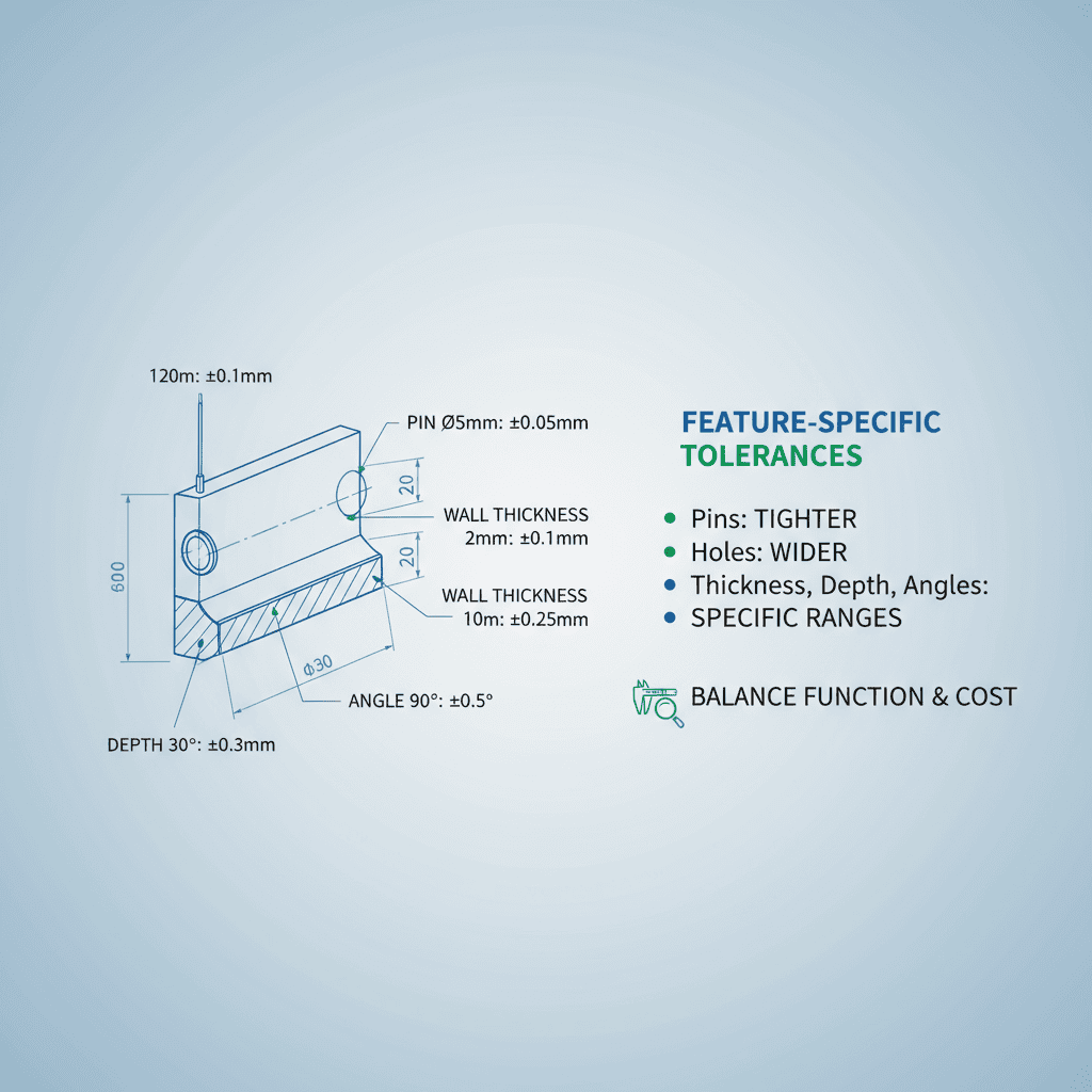
When we work with a client, especially a purchasing manager who needs to ensure parts from different suppliers fit together, we often talk about these feature-specific tolerances8. It's one thing to control the overall length and width of a part, but it's the functional details9 that make or break the assembly. Based on thousands of projects, we've learned what works and what is practical to manufacture consistently.
For example, a press-fit pin10 needs a very precise outer diameter to function correctly, so we aim for a tighter tolerance. In contrast, a clearance hole11 for a screw can have a slightly looser tolerance because its main job is just to let the screw pass through.
General Guide for Feature Tolerances
Here is a quick reference table of some common starting points we use. Remember, these can be adjusted based on the material and specific functional needs of your design.
| Feature Type | Dimension Range | Typical Commercial Tolerance (mm) |
|---|---|---|
| Hole Diameter | Ø < 10mm | ±0.1mm |
| Ø 10mm - 50mm | ±0.2mm | |
| Ø > 50mm | ±0.3mm | |
| Outer Diameter | Ø < 10mm | ±0.05mm |
| Ø 10mm - 50mm | ±0.1mm | |
| Ø > 50mm | ±0.2mm | |
| Depth / Thickness | General | ±0.05mm - ±0.2mm |
| Angle | General | ±0.5° - ±2° |
This structured approach helps us communicate clearly with our clients. We can identify the critical features that need the tightest control and allow for more standard tolerances elsewhere, optimizing the part for both performance and cost.
Conclusion
The right injection molding tolerance isn't a single number. It's a careful balance of material, size, and function, best determined through collaboration with your manufacturing partner for optimal results.
Understanding standard tolerances is crucial for ensuring the quality and fit of your molded parts. ↩
Commercial tolerances help balance cost and performance in the manufacturing process. ↩
Explore how different plastic materials impact tolerances to make informed choices for your projects. ↩
Learn about shrinkage rates to better predict the final dimensions of your molded parts. ↩
Understanding tolerance ranges helps in setting realistic expectations for your project. ↩
Dimensioning tables provide essential guidelines for calculating tolerances based on part size. ↩
Understanding the relationship between nominal size and tolerances is vital for design accuracy. ↩
Feature-specific tolerances are key to ensuring proper assembly and functionality of parts. ↩
Functional details can make or break assembly; understanding them is crucial for success. ↩
Learn about the specific tolerances needed for press-fit pins to ensure proper function. ↩
Explore the tolerance requirements for clearance holes to ensure smooth assembly. ↩