

Are you tired of seeing flawed parts come off the line? These defects cost time and money. It's a frustrating problem that stalls production and hurts your bottom line.
The most common injection molding defects include sink marks, flashing, weld lines, warping, and bubbles. These issues stem from imbalances in pressure, temperature, and material flow. Understanding the specific root cause of each defect is the first step to producing perfect parts consistently.
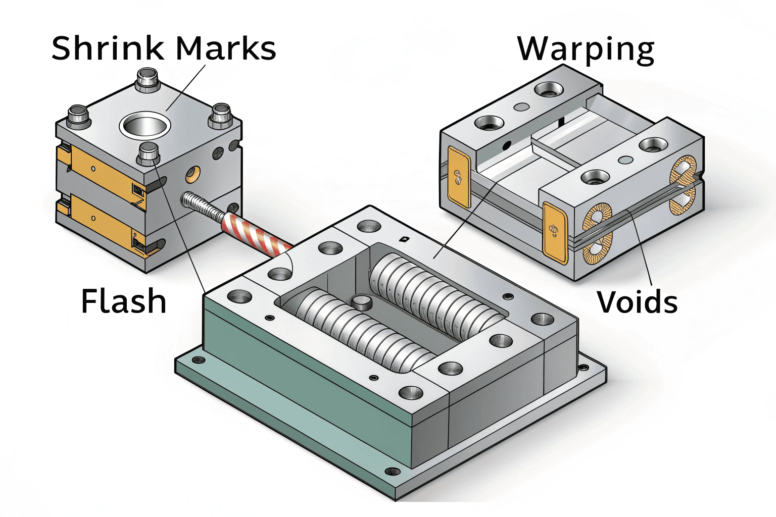

I've been in the custom molding business for 15 years. During that time, my team and I at Ambition Industrial have seen every defect imaginable. It's easy to get lost trying to solve these issues by just tweaking one or two settings on the machine. But the real solutions are often more nuanced and require a deeper understanding of what's happening inside the mold. Let's break down the most common problems I see and discuss the effective, real-world solutions that go beyond the basic operator's manual. We'll explore why these defects happen and how you can fix them for good.
How Can You Really Solve Annoying Sink Marks?
You see a noticeable dip on the surface of your finished part. This sink mark ruins the appearance and can even affect the part's function. It makes your high-quality product look cheap.
Sink marks are caused by a "balance mismatch" between material packing and cooling shrinkage. The key is to ensure the packing channel stays open long enough to feed the thicker sections as they cool, preventing the surface from collapsing inward. This requires more than just increasing pressure.

In my experience, many people immediately try to solve sink marks by cranking up the holding pressure. Sometimes this works, but often it just creates other problems. The real issue is a combination of insufficient material packing and uneven cooling. The core problem is that the path for the molten plastic to "pack" the part gets blocked before the thickest areas are solid. At the same time, these thick areas are cooling too quickly on the inside.
Breaking Down the Root Causes
The core conflict is simple: the material can't get to where it's needed most. This happens when the gate freezes off too early or the runner is too small.
| Common Misstep | Expert Solution |
|---|---|
| Only increasing holding pressure. | Switch to holding pressure when the mold is 95-98% full, not 100%. |
| Ignoring the mold's temperature. | Check the mold's surface temperature. A difference of more than 5°C can cause uneven shrinkage. |
| Placing the gate in a convenient spot. | Ensure the gate is near the thickest section of the part. This provides the best path for packing pressure. |
The most effective fix I've found is to optimize the flow path. We often recommend thickening the runner near the gate. This keeps the material molten longer, giving it more time to pack into the part and compensate for shrinkage. This approach is much more reliable than just increasing pressure, which can lead to flashing or stress in the part.
What Is the Real Reason for Flashing on Parts?
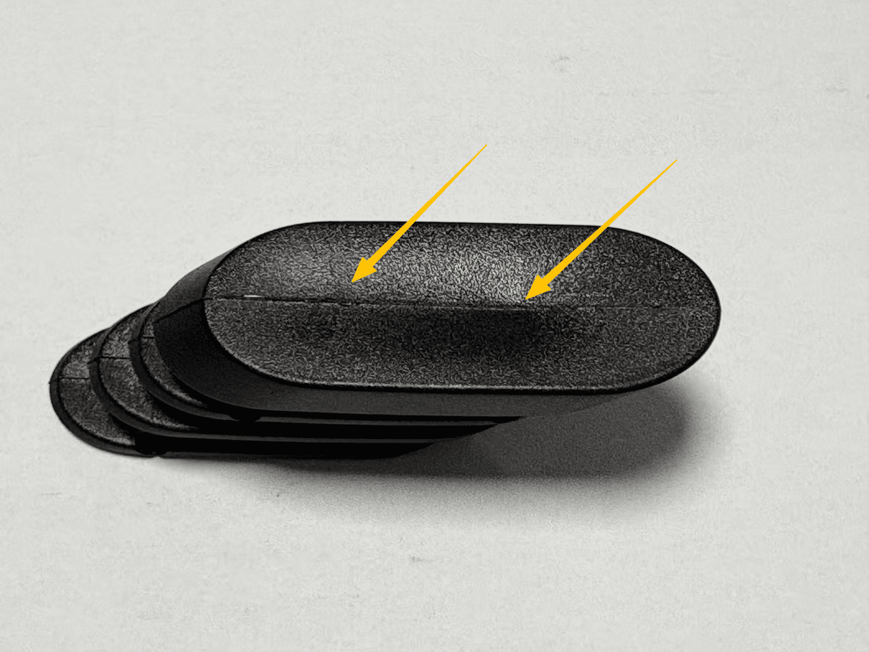
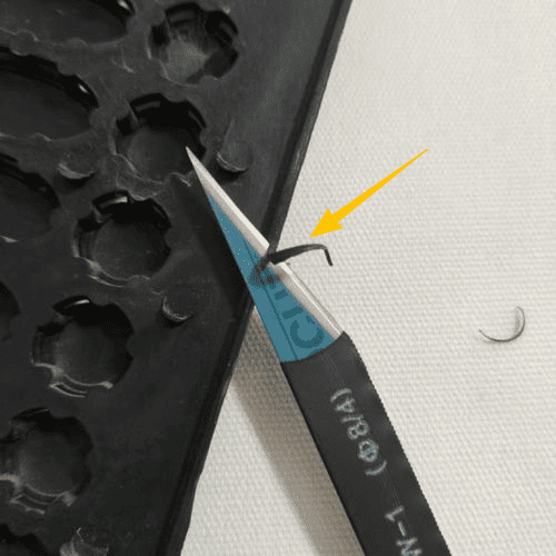
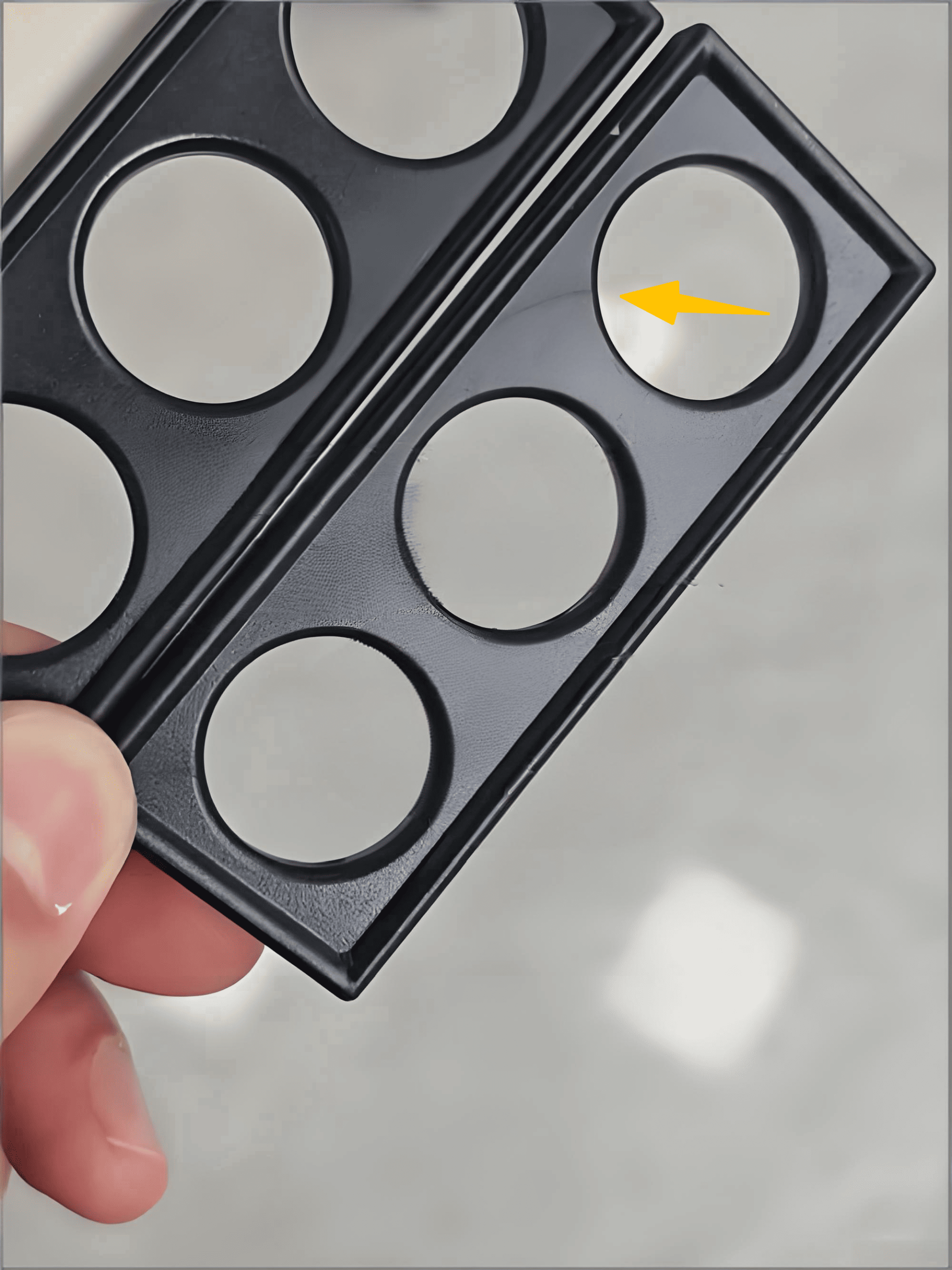
Flashing, that thin extra lip of plastic, appears on your parts. It means you have to pay for someone to manually trim every single piece. This slows down production and increases labor costs.
Flashing is caused by two main issues: the clamping force is too low to hold the mold shut, or the sealing surfaces of the mold are compromised. Even a tiny scratch or piece of residue on the parting line can allow molten plastic to escape.

When I see flashing, my first thought isn't just about the machine's clamping force. I’ve learned that the mold itself is often the culprit. Of course, the clamping force must be greater than the pressure of the plastic trying to push the mold open. But people often forget that the surfaces where the two halves of the mold meet have to be perfect. A tiny bit of grease, an old piece of plastic, or a microscopic scratch can create a gap. For high-flow materials like PP or PE, this is a very common problem.
The Double Test: Force and Sealing
You have to pass both tests to prevent flash. The machine needs enough force, and the mold surfaces must be perfectly clean and smooth.
Key Factors to Check
- Clamping Force Calculation: As a rule, we make sure the clamping force is at least 1.2 times the melt pressure multiplied by the part's projected area. This safety margin is critical.
- Parting Line Integrity: We regularly clean and polish the parting line of our molds. Any defect larger than 0.01mm is enough to cause a leak. You can't just rely on pressure to fix a bad seal.
- Melt Temperature: Another thing people overlook is the material temperature. If you increase the melt temperature by just 10°C, the material's viscosity can drop by about 15%. This makes it much more "runny" and far more likely to find any tiny gap and create flash. So, instead of just increasing clamp force, try controlling the melt temperature first. It’s a more precise and often more effective solution.
Why Do Unsightly Weld Lines Appear on Your Parts?
You see a fine line, almost like a crack, where two flows of plastic met. This weld line is a weak point and looks bad. It can cause parts to fail in the field.
Weld lines form when multiple streams of molten plastic meet but are too cool to fuse together properly. The solution lies in managing the meeting angle of the plastic flows and the temperature at the point of fusion, not just the overall melt temperature.

A common mistake I see engineers make is to simply increase the barrel temperature. They think hotter plastic will solve the problem. But this often doesn't work because the issue isn't the starting temperature. The problem is how much heat is lost as the plastic travels through the mold. The "flow fronts" cool down before they meet. And if they meet at a sharp angle, they don't have enough surface area to bond strongly. It's a problem of temperature and geometry at the exact point of contact.
The Secret Code of Fusion
To get a strong, invisible weld, you need the right temperature and the right meeting angle. It's like a secret code for the material.
| Common Misstep | Expert Solution |
|---|---|
| Only increasing the overall melt temperature. | Place a heating rod in the mold near the weld line to keep that specific area hot. |
| Ignoring the flow path design. | Redesign the gate locations so the plastic flows meet at an angle of 135° or more. |
| Assuming the material is fine. | Add a small amount (around 5%) of a compatibilizer agent to the material to help it bond better. |
The most successful technique we've used at Ambition Industrial is to control the meeting angle. By changing the gate position, we can make the plastic flows merge at a wider angle, like 135° or more. This gives them more surface area and time to fuse. We also sometimes add small heating elements inside the mold right where the weld line forms. This keeps that specific spot hot, ensuring a perfect bond. This is a much more targeted and effective solution than just turning up the heat on the whole process.
Is There a Reliable Way to Prevent Warping?
Your parts come out of the mold looking twisted or bent. This warping makes them impossible to assemble or use. It's a huge waste of material and machine time, and it's frustrating to solve.
Warping is the result of unevenly released stress inside the part. This stress is created by differences in material shrinkage and shear from the filling process. The key is to balance these stresses during cooling, not just cool the part for a longer time.

I've seen many teams try to fix warping by simply extending the cooling time. This rarely solves the root cause. The part is fighting an internal battle. On one side, you have shear stress caused by the plastic molecules being stretched as they're injected too fast. On the other side, you have shrinkage stress, especially when a part has thick and thin walls. A wall thickness ratio greater than 3:1 can create a shrinkage difference of 20%, which is a massive amount of internal force pulling the part out of shape. The part warps when these stresses are released unevenly as it cools.
Balancing the Internal Stresses
The goal is not to eliminate stress completely, but to make sure it's uniform throughout the part. When the stress is balanced, the part stays flat.
A Three-Pronged Attack on Warping
- Gradient Cooling: We design our cooling channels to cool the part unevenly on purpose. We use warmer water to cool the thick sections slowly and colder water to cool the thin sections quickly. This makes everything shrink at a more similar rate.
- Variable Injection Speed: Instead of injecting at one constant speed, we use a "slow-fast-slow" profile. We start slow to reduce stress at the gate, speed up to fill the part quickly, then slow down at the end to pack gently. This minimizes the molecular stretching that causes shear stress.
- Ejector Pin Placement: The final step is how the part is pushed out. We ensure our ejector pins are placed symmetrically and push on strong, supported areas. This releases the part from the mold without introducing any new, localized stress.
How Can You Differentiate Voids and Gas Bubbles?
You find bubbles inside your plastic parts during quality control. Are they a sign of a packing problem or a gas problem? Choosing the wrong solution wastes time and doesn't fix the issue.
You must accurately tell the difference between a vacuum void and a gas bubble. Voids are smooth, round bubbles in thick sections caused by poor packing. Gas bubbles are irregular shapes near the surface caused by trapped air, moisture, or burnt plastic.

This is one of the most common points of confusion I encounter. People see a bubble and assume it's trapped air. They start working on the mold's venting, but the problem doesn't go away. That's because they might be looking at a vacuum void, which is an entirely different issue. A void is basically a shrinkage hole. It forms in the center of a thick section when there isn't enough plastic packed in to compensate for shrinkage as it cools. A gas bubble, on the other hand, is literally trapped gas from poor venting, wet material, or the plastic itself degrading from too much heat.
Pinpointing the True Cause
Knowing what kind of bubble you have tells you exactly where to look for the solution. It saves a lot of guesswork.
| Bubble Type | Location & Appearance | Root Cause | Solution |
|---|---|---|---|
| Vacuum Void | Center of thick sections, round, smooth. | Insufficient packing pressure or time. | Increase holding pressure/time, widen gates/runners. (Similar to fixing sink marks). |
| Gas Bubble | Near the surface or gate, irregular shape. | Poor venting, wet material, overheating. | Add vents (0.01-0.02mm deep), properly dry raw material (e.g., ABS at 80°C for 4 hours), lower barrel temp. |
The first thing we do is cut the part open. If the bubble is perfectly round and shiny on the inside, and it’s right in the middle of the thickest wall, it's a void. We then focus on improving packing. If the bubble is an odd shape and near the surface, it’s a gas bubble. Then we check our material drying logs and inspect the mold vents. This simple diagnosis step is critical to solving the problem quickly.
Conclusion
Solving molding defects requires looking past simple fixes. By understanding the root causes of sink marks, flashing, and warping, you can produce better parts and save significant time and money.