
Your perfect car interiors are being ruined by small flaws. These defects lead to customer complaints and high costs. Understanding these issues is the first step to fixing them.
The most common defects are sink marks, flash, flow marks, color variations1, bubbles, and warpage. These issues come from problems in mold design, material choice, or the injection molding process itself. Fixing them requires a deep understanding of manufacturing.

These small flaws can turn a premium product into a discounted item. As a manufacturer with 15 years of experience, I've seen it all. I've worked with many procurement managers who were struggling with quality control from their previous suppliers. They came to us frustrated and worried about their brand's reputation. Let's look at each of these defects one by one. I will explain what they are, why they happen, and how we solve them for our clients. This will help you get the quality you pay for.
How do you get rid of sink marks2 on your dashboards?
That beautiful dashboard surface is marred by ugly dips. This makes your product look cheap and poorly made. There is a clear path to getting a perfectly smooth finish.
Sink marks are small depressions on the surface of a part. They are caused by uneven plastic shrinkage as it cools. You can fix them by optimizing wall thickness, increasing holding pressure, and ensuring the mold's cooling is uniform.
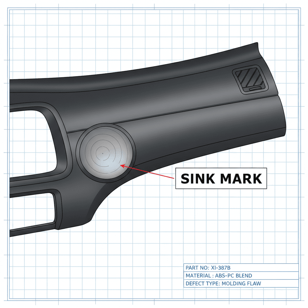
I remember a project with a client developing a new center console. Their first samples were covered in sink marks, especially right above the support ribs. They were worried about production delays. The problem was a classic design flaw. The ribs were too thick compared to the main wall. This creates hot spots where the plastic takes longer to cool and shrinks more, pulling the surface down. We worked with their design team to adjust the part. We didn't just tell them to "fix it." We showed them exactly how. We reduced the thickness of the ribs to about 60% of the main wall thickness. We also optimized the gate location to ensure pressure was applied effectively to these areas during the cooling phase. This simple change, combined with adjusting our machine's holding pressure, completely eliminated the sink marks.
| Parameter | Problematic Approach (Causes Sink Marks) | Optimized Solution (Prevents Sink Marks) |
|---|---|---|
| Wall Thickness | Abrupt changes, overly thick sections. | Gradual transitions, uniform thickness. |
| Rib Design | Rib thickness > 70% of wall thickness. | Rib thickness is 50-60% of wall thickness. |
| Holding Pressure | Too low or holding time is too short. | Sufficient pressure and time to pack out the part. |
| Mold Temperature | Too high, causing slow, uneven cooling. | Controlled and uniform for consistent cooling. |
Why does ugly flash ruin your car door trims?
You've got your parts, but they have messy, sharp edges. This extra plastic, called flash3, needs to be manually trimmed. It wastes time, costs money, and risks damaging the part.
Flash is a thin layer of excess plastic that escapes from the mold cavity. It's usually caused by insufficient clamping force, a worn-out mold, or injection pressure that's too high. Proper mold maintenance and precise process control are key to preventing it.
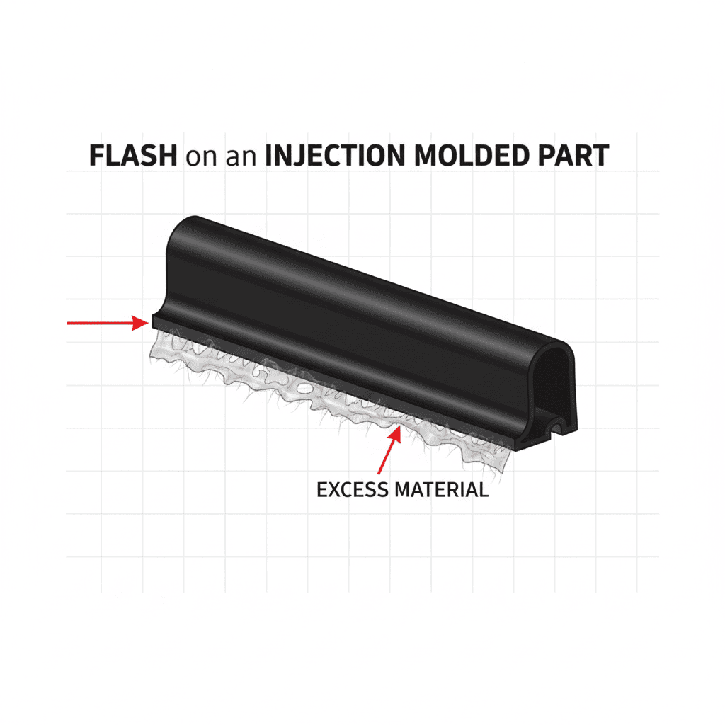
Flash is one of the most frequent headaches for buyers. A client in the automotive sector came to us with door panel trims that had persistent flash issues. Their previous supplier kept blaming the machine, but the problem was deeper. When we inspected their mold, we found that the parting line surfaces were worn down. After thousands of cycles without proper maintenance, small gaps had formed. It doesn't matter how high you set the clamping force if the mold doesn't seal perfectly. We re-machined the parting line surfaces to restore a perfect seal. We also analyzed their process. The injection pressure was unnecessarily high. By lowering the pressure and matching it correctly to a sufficient clamping force, the flash disappeared. It's a balance. Too much pressure forces plastic out, but too little can cause other defects.
| Factor | Common Cause of Flash | How to Prevent Flash |
|---|---|---|
| Clamping Force | Not high enough to keep the mold shut against pressure. | Calculate and apply force that exceeds injection pressure. |
| Mold Condition | Worn or damaged parting lines, bent mold plates. | Regular maintenance, cleaning, and timely repairs. |
| Injection Pressure | Set too high, forcing plastic into gaps. | Optimize pressure to the minimum needed for a full part. |
| Vent Depth | Vents are too deep, allowing plastic to escape. | Machine vents to spec, typically 0.02-0.03mm for ABS. |
What causes those wavy flow marks on plastic surfaces?
Your part's surface should be glossy and uniform. Instead, you see wavy, dull patterns, especially near the injection point. These flow marks4 make a high-end part look low-quality.
Flow marks are visible patterns on the part surface that trace the path of the molten plastic. They are often caused by low melt temperature, slow injection speed, or poor mold flow path design. Increasing temperature and injection speed helps eliminate them.
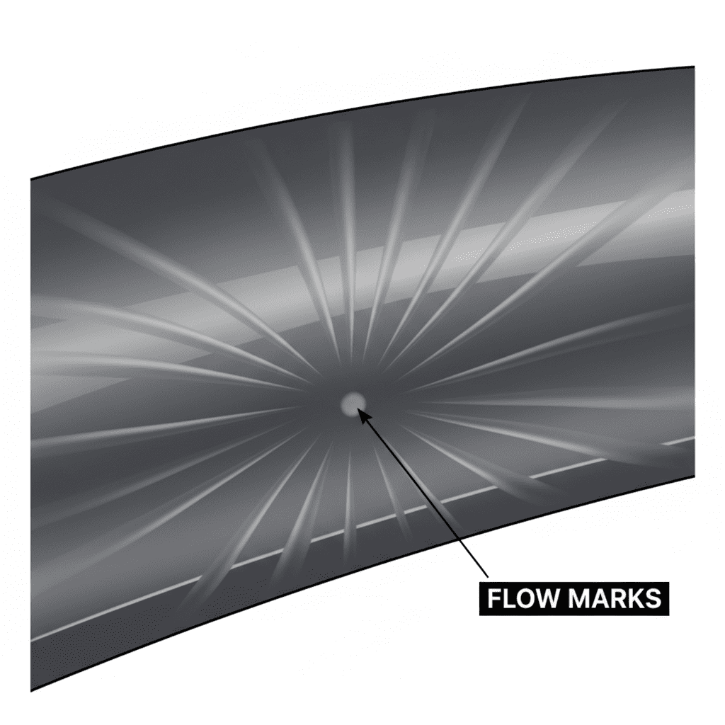
We once helped an electronics developer who was making a high-gloss black cover for a car's infotainment system. The part had to be perfect. Their samples had noticeable flow marks that looked like ripples on a pond. The issue was that the plastic was cooling down too quickly as it flowed through the mold. The mold's channels were long and thin, and the injection speed was too slow. The plastic's "flow front" would hesitate and start to solidify before the mold was completely full, creating those marks. We tackled this in two ways. First, we increased the melt temperature and the mold temperature. This kept the plastic hotter and more fluid for longer. Second, we significantly increased the injection speed. This pushed the plastic into the cavity so fast it had no time to hesitate. The result was a beautiful, mirror-like finish with no flow marks.
| Process Parameter | Poor Setting (Causes Flow Marks) | Optimal Setting (Prevents Flow Marks) |
|---|---|---|
| Melt Temperature | Too low, making plastic too viscous. | Raised to improve flow characteristics. |
| Injection Speed | Too slow, allowing the flow front to cool. | Fast enough to fill the cavity quickly. |
| Mold Temperature | Too cool, solidifying plastic prematurely. | Increased to maintain melt flow. |
| Gate/Runner Design | Poorly placed or too small, restricting flow. | Designed for smooth, unobstructed flow. |
Is color mismatch making your interior parts look cheap?
You ordered 1,000 beige door handles. But when you get them, some are slightly darker, some are lighter. This inconsistency across a car's interior instantly screams low quality to a customer.
Color variation is a difference in color between parts from the same batch or different batches. It is caused by poor mixing of colorant, fluctuating process temperatures, or using different batches of raw material. Strict process control and material management are essential.
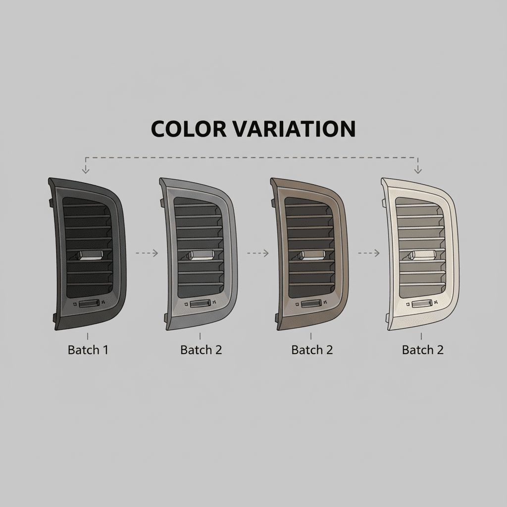
This is a critical issue, especially for automotive clients who need dozens of parts from different suppliers to match perfectly. I worked with a brand manager for a toy company who had this exact problem with their STEM products. The signature color of their brand was a specific shade of blue. Their supplier was delivering parts that were all over the place. We found two root causes. First, their supplier was not mixing the color concentrate with the base plastic resin thoroughly. They were just "tumble mixing" it in a bucket. We use gravimetric blenders that dose the colorant precisely and ensure it's perfectly distributed. Second, their molding machine's temperature was fluctuating. Even a 10°C swing can change the final shade of some pigments. We implemented strict process monitoring to keep the barrel temperature stable within ±2°C. Consistent color comes from consistent processes.
| Area of Control | Source of Color Variation | Best Practice for Consistency |
|---|---|---|
| Material Mixing | Inconsistent ratio of colorant to base resin. | Use automated gravimetric blenders for precise mixing. |
| Process Temperature | Barrel temperature fluctuations alter pigment shade. | Monitor and maintain a stable temperature profile. |
| Raw Materials | Using different batches of resin or colorant. | Qualify and use a single batch of material for a production run. |
| Drying | Improper or inconsistent drying of materials. | Dry all materials to the manufacturer's specification before molding. |
Are tiny bubbles and pinholes weakening your parts?
You inspect a part that looks good from a distance. But up close, you see tiny holes on the surface, or you break it and find a large void inside. These bubbles5 compromise both appearance and strength.
Bubbles and pinholes are voids trapped in the plastic. They are usually caused by moisture in the raw material that turns to steam, or by gas that cannot escape the mold. Proper material drying and good mold venting are the solutions.
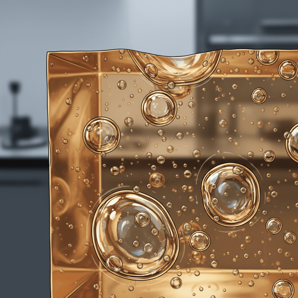
Many plastics, like ABS, PC, and Nylon, are "hygroscopic," meaning they absorb moisture from the air. If you don't dry them properly before molding, that water turns into steam inside the hot machine barrel. This steam gets trapped in the plastic, forming bubbles5. I remember a case with a thick-walled part, an armrest support. The client's parts were failing strength tests. When we cut one open, it was full of internal bubbles. Their previous supplier wasn't drying the PC resin correctly. We showed them the data. We put their "ready-to-use" material in our moisture analyzer, and it had ten times the recommended moisture content. We implemented a strict drying protocol: 4 hours at 120°C. That alone solved 90% of the problem. We also checked the mold's vents to make sure any remaining air could get out. This combination is key for solid, strong parts.
| Defect Type | Primary Cause | Solution |
|---|---|---|
| Pinholes (Surface) | Trapped gas or air at the mold surface. | Improve mold venting6; optimize injection speed. |
| Internal Bubbles | Moisture in the plastic material turning to steam. | Thoroughly dry raw materials7 according to specifications. |
| Voids (Thick Sections) | Shrinkage pulling the part apart from the inside. | Increase holding pressure and time to pack out the section. |
| Gas Traps | Air pocketed in a corner with no escape path. | Add vents or an overflow tab at the last point to fill. |
Why do your large interior panels bend and warp?
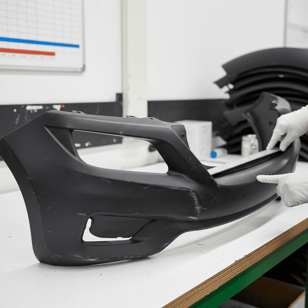
You receive a shipment of large, flat parts like door panels or dashboard covers. But when you try to install them, they don't fit. They are twisted or bent, a classic case of warpage8.
Warpage is the distortion of a part after it has been ejected from the mold. It is caused by non-uniform cooling, internal stresses from material shrinkage, or improper ejection. A well-designed cooling system9 and a balanced part design are crucial.
Warpage is a battle against physics. As plastic cools, it shrinks. If one part of a component cools and shrinks faster than another, it creates stress, and that stress pulls the part out of shape. We worked on a large lower dashboard panel for an automotive client. Their initial design was a huge, flat piece with ribs on one side. The ribbed side was much stiffer and cooled differently than the flat, cosmetic side. The result was a part that curled up like a potato chip. We couldn't just change the material; we had to change the design. We worked with them to add symmetrical design features and, most importantly, we designed a sophisticated cooling system in the mold. We ran more cooling lines on the hotter, more insulated side of the mold to balance the cooling rate. It's like a race: you have to make sure every part of the plastic cools and crosses the finish line at the same time.
| Factor | Cause of Warpage | How to Prevent Warpage |
|---|---|---|
| Cooling System | Uneven mold temperature; fewer cooling lines on one side. | Design a balanced cooling layout to ensure uniform temperature. |
| Part Design | Large variations in wall thickness; non-symmetrical features. | Maintain uniform wall thickness; add features symmetrically. |
| Material Shrinkage | Using high-shrinkage materials without accounting for it. | Choose low-shrinkage or glass-filled materials; adjust mold design10. |
| Ejection | Ejecting the part too hot or with uneven force. | Allow for adequate cooling time |
Consistent color is vital for brand reputation; learn how to achieve it effectively. ↩
Understanding sink marks is crucial for improving part quality and reducing customer complaints. ↩
Preventing flash can save time and costs, ensuring a cleaner production process. ↩
Eliminating flow marks enhances the aesthetic quality of your products, making them more appealing. ↩
Preventing bubbles ensures stronger, more reliable parts, enhancing overall product quality. ↩
Proper venting is essential for preventing defects like bubbles and ensuring smooth production. ↩
Choosing the right raw materials is essential for achieving high-quality, defect-free products. ↩
Understanding warpage helps in designing better parts that fit correctly and maintain integrity. ↩
A well-designed cooling system is crucial for preventing warpage and ensuring part quality. ↩
Good mold design is key to preventing defects and ensuring high-quality production. ↩