跳到内容
跳到内容 

Struggling with PC injection molding? Getting defects like silver streaks or cracks? You need a reliable process to get perfect parts every time, and I can show you how.
To master PC injection molding, focus on proper drying, low-shear plasticization, and precise temperature control. Key parameters include a mold temperature of 80-120°C and a melt temperature between 260-320°C. This prevents defects and ensures part stability.

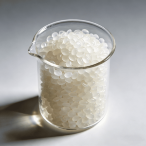
I’ve spent 15 years in this industry, and I’ve seen it all. Polycarbonate (PC) is a fantastic material, but it's also famously picky. It doesn't forgive mistakes. Many people treat it like any other plastic, and that’s where the problems begin. But once you understand its unique personality, you can make it work for you, not against you. Let's dive into the details that separate a beginner from a pro and turn your production challenges into successes.
How Do You Master PC's High Viscosity During Plasticization?
Are your PC parts showing degradation? High viscosity makes it tricky. Incorrect machine settings can ruin the material, leading to costly waste and production delays for your project.
Master PC's viscosity by using a "low shear, full plasticization" strategy. This means using a screw with a 2.5-3.0:1 compression ratio and keeping back pressure low, around 0.3-0.8 MPa. This ensures the material melts properly without being damaged.

I remember a client who was developing high-end electronic casings. Their parts were coming out brittle and failing basic drop tests. They looked perfect, but they had no strength. When my team at Ambition Industrial investigated, we found their machine's back pressure was set way too high. They thought they needed to force the thick, high-viscosity PC to melt faster. Instead, they were literally tearing the material's molecular chains apart with excessive shear force. This is a common trap. You have to be gentle with PC.
The Core Logic: Low Shear + Full Plasticization
Polycarbonate has long, strong molecular chains. That's what gives it its amazing impact resistance. But high shear, which is intense friction and pressure inside the machine barrel, acts like a pair of scissors. It chops these long chains into shorter ones, permanently weakening the material. The goal is to melt the plastic pellets thoroughly (full plasticization) using heat and gentle mixing, not brute force. You also must dry the material properly. If the water content is above 0.02%, the water turns to steam at processing temperatures and reacts with the PC. This chemical reaction, called hydrolysis, also breaks the molecular chains and leaves ugly silver streaks on your part's surface.
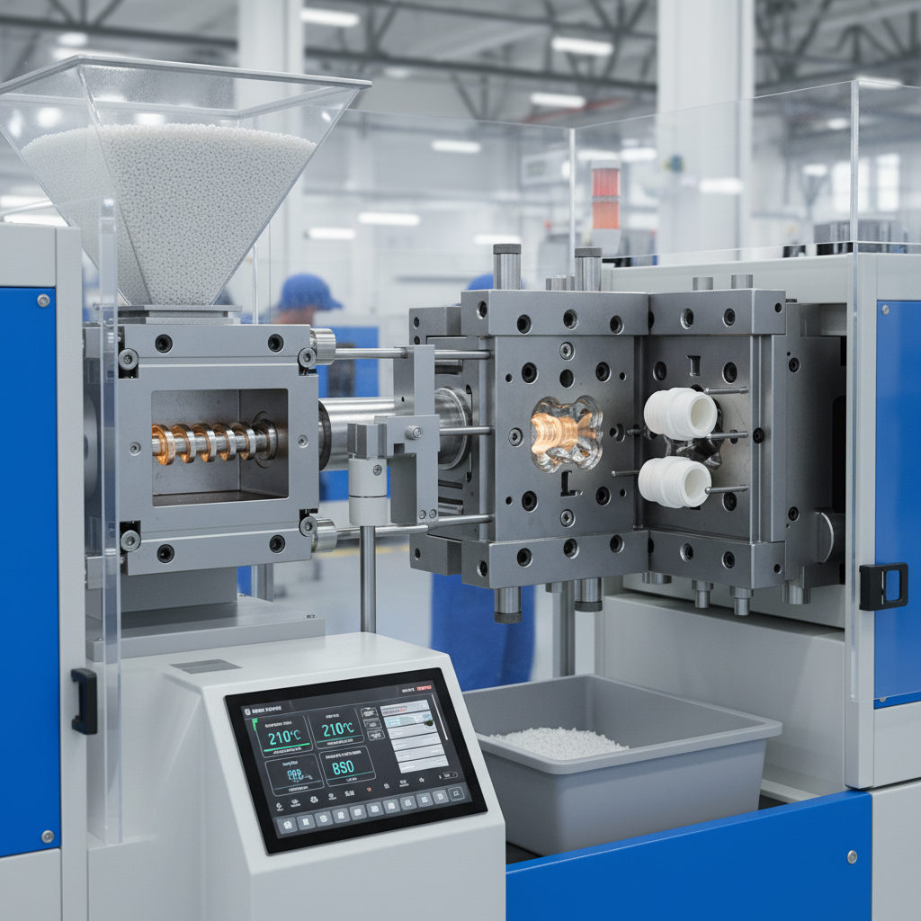
Setting the Right Machine Parameters
Achieving this "gentle but thorough" approach comes down to a few critical settings. It's a balancing act.
| Parameter | Recommended Range | Why It Matters |
|---|---|---|
| Drying (Water Content) | < 0.02% | Prevents hydrolysis. This reaction causes silver streaks and makes the final part brittle. |
| Screw Compression Ratio | 2.5 - 3.0:1 | Balances melting efficiency with shear. Too low, and the plastic doesn't melt evenly. Too high, and the shear is excessive. |
| Back Pressure | 0.3 - 0.8 MPa | Provides gentle resistance for uniform melting but keeps shear low. High back pressure leads to material degradation. |
Is Your Mold Design Causing Hidden Stress in PC Parts?
Are your seemingly perfect PC parts cracking after assembly? The problem might not be the molding process, but the mold itself. Poor design creates internal stress that leads to failure.
Yes, poor mold design is a major cause of stress. Ensure gate cross-sections are at least 30% larger than for other plastics. Also, keep cooling channels close together (≤15mm) and near the cavity to ensure uniform cooling.

We once worked with an educational toy developer. Their new line of building blocks, made from colorful PC, was failing impact tests. The parts shattered easily. As a company that prides itself on creating durable STEM products, this was a disaster for their brand. We analyzed their mold. The design was fine for a material like ABS, but not for PC. The gates were too small, and the cooling channels were too far apart. These two things were building massive stress into every single part. The parts were doomed before they even left the mold.
The Gate: Your First Line of Defense Against Shear
The gate is the small opening where the molten plastic enters the mold cavity. Think of it as a doorway. For a thick, high-viscosity material like PC, a small doorway creates a huge bottleneck. The plastic is squeezed and sheared intensely as it's forced through. This high-shear point creates a weak spot right at the gate, which is often where cracks begin. By making the gate's cross-sectional area at least 30% larger than you would for a general-purpose plastic, you create a wider door. The plastic can flow in more gently, reducing shear and preventing that initial damage.
Cooling Channels: The Key to Uniformity
Once the mold is filled, it needs to cool. If one area of the part cools much faster than another, it creates a tug-of-war inside the plastic. The fast-cooling section shrinks and solidifies while the hot section is still soft. This pulls on the material, creating internal stress. To prevent this, your cooling channels must be close to the cavity surface and spaced no more than 15mm apart. This creates an even cooling profile across the entire part, so everything shrinks at a similar rate, minimizing stress.
| Mold Feature | Bad Design (High Stress) | Good Design (Low Stress) |
|---|---|---|
| Gate Cross-Section | Standard size (like for PP/ABS) | At least 30% larger than standard |
| Cooling Channel Spacing | > 15mm apart | ≤ 15mm apart |
| Channel Placement | Far from the cavity surface | Close and conforming to the cavity's shape |
Are You Balancing Melt and Mold Temperatures Correctly for PC?
Getting sink marks or long cycle times with PC? Your temperatures are likely out of sync. This common mistake compromises both part quality and your production efficiency.
For optimal PC molding, you must coordinate melt and mold temperatures. A low mold temperature (<80°C) causes sink marks, while a high one (>120°C) slows production. Sync your melt temp (260-320°C) with the right mold temp (80-120°C).

This concept of "dual temperature synergy" is something I drill into every new engineer. You can't just focus on one temperature. I saw this firsthand with a cosmetics packaging client. They wanted a premium, flawless finish on their PC jars. But their parts had slight indentations, or sink marks, on the thick-walled sections. They had the melt temperature correct, but their mold temperature was too low, around 65°C. They were trying to speed up the cycle time. The cold mold surface froze the outer skin of the part instantly, but the molten core continued to cool and shrink, pulling the soft skin inward.
The "Dual Temperature Synergy" Principle
Think of it this way: the melt temperature (260-320°C) makes the plastic fluid enough to flow and fill the entire mold. The mold temperature (80-120°C) keeps the plastic from freezing too quickly. A warm mold allows the plastic to pack into every corner and detail before it solidifies. This ensures a complete, well-formed part without surface defects. If the mold is too cold (<80°C), you get sink marks and poor surface finish. If the mold is too hot (>120°C), the part takes too long to cool down, killing your cycle time and efficiency.
Adjusting for Wall Thickness
This balance also depends on the part's geometry. Thicker walls take longer to cool. A good rule of thumb we use at Ambition Industrial is to increase the mold temperature by 5-8°C for every 1mm increase in wall thickness. This gives the thicker section enough time to pack out fully and cool from the inside out, preventing voids and sink marks.
| Scenario | Mold Temperature | Melt Temperature | Resulting Defect |
|---|---|---|---|
| Cold Mold | < 80°C | 260-320°C | Surface sink marks, poor replication of detail |
| Hot Mold | > 120°C | 260-320°C | Long cycle times, potential for part deformation |
| Low Melt Temp | 80-120°C | < 260°C | Short shots (unfilled parts), high internal stress |
| High Melt Temp | 80-120°C | > 320°C | Material degradation, yellowing, gas marks |
How Can You Detect Invisible Stress Before PC Parts Fail?
Your PC parts look perfect, but are they failing in the field? Hidden internal stress is a silent killer, leading to unexpected cracks and expensive product recalls for your business.
You cannot see internal stress with your eyes. Use a chemical test: dip the part in ethyl acetate for 10-15 seconds. If micro-cracks appear, you have high stress. Or, use a polarized light microscope to see stress patterns.

This is one of the most important lessons in quality control for PC. I had a client in the automotive industry whose beautiful, glossy interior trim pieces were cracking a few months after installation in cars. Their parts looked flawless coming off the machine. The dimensions were perfect, the surface was perfect. But they were failing. We took one of their parts and dipped it in a bath of ethyl acetate. It was covered in tiny cracks, a phenomenon called crazing, almost instantly. The stress was built into the part from the very beginning, just waiting for a change in temperature or a slight vibration to cause a failure.
Why Visual Inspection Isn't Enough
Internal stress is a microscopic problem. It’s a result of the polymer molecules being frozen in a stretched or compressed state during the molding process. You can't see it. A part can pass every visual and dimensional check and still be a ticking time bomb. This is why you must have a method to check for this "invisible" defect, especially when you are setting up a new mold or process. You need to look for stress in areas where it concentrates, like near the gate, at sharp corners, and where the wall thickness changes suddenly.
Practical Methods for Stress Detection
You don't need a million-dollar lab to check for stress. There are two very effective methods.
| Test Method | How It Works | What to Look For |
|---|---|---|
| Ethyl Acetate Immersion | This simple solvent attacks the high-energy, stressed areas of the polymer first. | Micro-cracks (crazing) appearing on the surface within 10-15 seconds. The faster they appear, the higher the internal stress. |
| Polarized Light Microscopy | Because PC is transparent, stress inside the material bends light. Polarizing filters make this bending visible. | Rainbow-like patterns (photoelastic fringes). Dense, colorful patterns indicate high-stress concentration zones. |
What Are the Rules for Safely Reusing Recycled PC Material?
Trying to save costs with recycled PC? Using it incorrectly can destroy your product's quality, leading to brittle parts and ruining your brand's reputation for reliable products.
Use recycled PC (regrind) carefully. Never use 100% regrind if its Melt Flow Rate (MFR) has changed by over 15% from the virgin material. When mixing, keep the regrind ratio below 30% and add 20-30 minutes of extra drying time.

Using regrind is great for sustainability and cost reduction, but you have to respect the material. I consulted for a startup making eco-friendly toys. They wanted to use 50% recycled PC to boost their green credentials. But their parts kept failing basic drop tests. We tested the MFR of their regrind. MFR is a measure of how easily the plastic flows when melted. Their regrind's MFR had jumped by 25% compared to the new material. This told us the plastic was severely degraded. The long molecular chains had been broken down into short ones, making the material weak and brittle.
Understanding Performance Degradation
Every time you heat, shear, and cool PC, you cause a little bit of damage. The degradation rate is about 3-5% per cycle. The material's viscosity drops, and its MFR goes up. This means the polymer chains are getting shorter. Shorter chains mean lower impact strength, lower toughness, and a more brittle part. You can't recycle PC forever and expect it to perform like new. There is a clear limit. The 15% change in MFR is a critical threshold that tells you the material is no longer structurally reliable on its own.
The Golden Rules of PC Regrind Usage
To use regrind safely and effectively without compromising quality, my team and I always follow a strict set of rules. These rules protect the final part's integrity and ensure we deliver the high quality our clients expect. You also have to remember that regrind, which is ground-up runners and rejected parts, has more surface area than neat pellets. This means it absorbs moisture much more easily, so extra drying is not optional—it's essential.
| Guideline | The Rule | The Reason |
|---|---|---|
| Performance Threshold | Stop using 100% regrind if its MFR has changed by more than 15%. | A significant MFR change indicates severe material degradation, which leads directly to brittleness and part failure. |
| Mixing Ratio | Keep the regrind percentage below 30% when mixing with new material. | This dilutes the effect of the degraded material, helping to maintain acceptable overall part performance and strength. |
| Extra Drying | Add 20-30 minutes to your standard drying time for the blend. | Regrind particles have more surface area and absorb more moisture, which must be removed to prevent silver streaks and brittleness. |
Conclusion
Mastering PC requires controlling plasticization, mold design, temperatures, stress, and regrind use. Focus on these key areas, and you will produce high-quality, reliable parts every single time.