
Designing a mold for a complex plastic part feels impossible. A small mistake can lead to huge costs and delays. But with the right strategy, you can turn a challenge into a success.
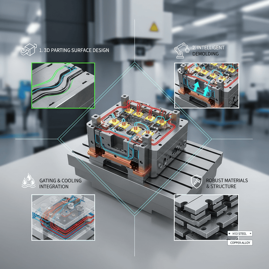
The key is to master four areas. First, design the parting surface1 with a 3D mindset. Second, create an intelligent demolding system2. Third, integrate gating and cooling3. Finally, choose robust materials and a solid structure. This approach ensures quality and efficiency for even the most complex parts.

When I first started, I thought of mold design as just creating a cavity. But a project for an automotive client, involving a dashboard component with multiple curves and textures, taught me a hard lesson. The initial design failed spectacularly, with defects everywhere. That failure forced me to rethink my entire process. I realized that designing a mold for a complex part is less about just shaping steel and more about predicting and controlling the physics of plastic. It's a system where every element is connected, and success depends on getting every one of those connections right from the very start. Let's walk through the lessons I learned.
How should you design the parting surface for a complex part?
A simple parting line on a complex part often leaves an ugly seam. This can ruin the product's appearance and lead to customer rejections. The secret is to think in 3D.
Design the parting surface to follow the part's shape, not just a flat plane. This strategy keeps the parting line off cosmetic faces, helps air escape during injection, and often simplifies the entire mold structure.
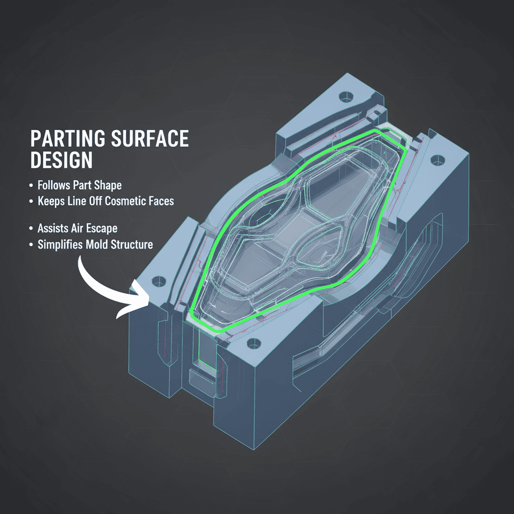
The parting surface is like a "spatial scalpel" that cleanly separates the mold halves to release the part. For a complex part, this "cut" is rarely a straight line on a flat plane. We have to think in three dimensions to find the best path. A well-designed parting surface is the foundation for a successful mold. It directly impacts the part's final look, the mold's reliability, and manufacturing costs. Getting it right means looking at the part from every angle and finding the one path that solves the most problems. This single decision can prevent a cascade of issues later on.
Key Considerations for Parting Surface Design
| Factor | Poor Design (Flat Plane) | Smart Design (Spatial Surface) |
|---|---|---|
| Appearance | Line cuts across visible, high-gloss surfaces, leaving a mark. | Line is hidden in a corner or follows a texture change. |
| Venting | Traps air in thin sections, causing burn marks or incomplete fill. | Placed to allow natural air escape from the cavity. |
| Structure | Requires extra sliders and lifters, increasing complexity and cost. | Simplifies the mold, reducing the need for moving parts. |
| Demolding | Part may stick to the wrong side of the mold, complicating ejection. | Ensures the part reliably stays on the ejector side of the mold. |
We always prioritize keeping the parting line away from the main cosmetic faces of a product. Even a tiny mismatch in the mold halves, called flash4, is very difficult to clean up on a curved or textured surface without leaving a trace. A smart parting surface also simplifies the mold's mechanics. By carefully choosing its path, we can often avoid the need for complex mechanisms like sliders or lifters, which are common failure points. This not only makes the mold more reliable but also reduces the cost and time needed to build it. It’s a strategic choice that pays off throughout the entire life of the tool.
How do you get a complex part out of the mold without damage?
Complex parts with undercuts and deep sections tend to get stuck in the mold. Trying to force them out with simple pins can cause ugly stress marks, warping, or even breakage.
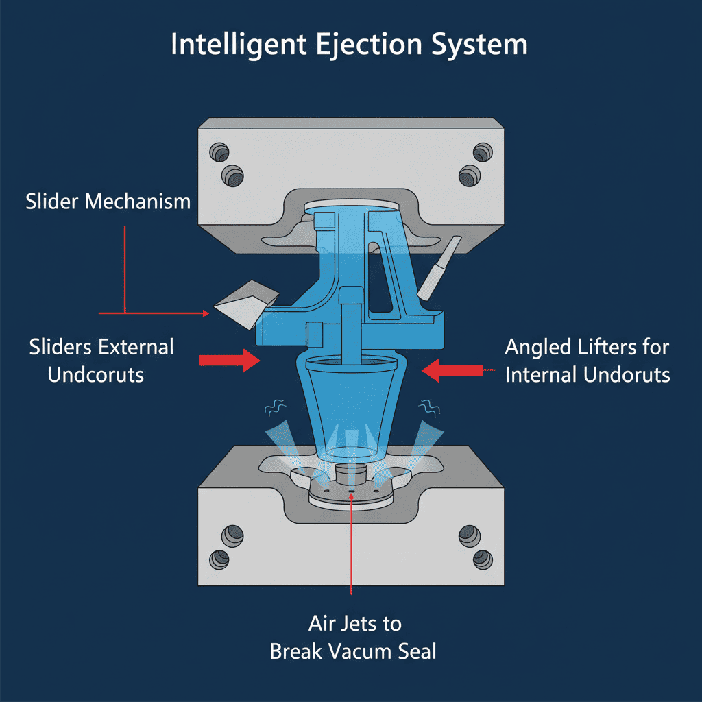
Instead of using brute force, you need an intelligent ejection system. Analyze where the part grips the mold. Use sliders for external undercuts and angled lifters for internal ones. For deep parts, add air jets to break the vacuum seal.
As plastic cools, it shrinks and grips onto the mold core, creating a strong "wrapping force." For a simple box shape, this force is easy to predict. But for a complex part with ribs, holes, and curves, the force is uneven and powerful. The goal of the demolding system is not to fight this force, but to release it strategically. We have to design mechanisms that gently unhook the part from every feature that grips it. This requires us to foresee exactly where and how the part will stick. I remember a project for an electronics housing with internal snap-fits. Our first attempt to eject it with standard pins just broke the delicate snaps. We had to redesign the system with small, precise lifters that moved at an angle, unhooking the snaps before pushing the part out. This experience taught me that ejection is a delicate dance, not a strong push.
Solving Demolding Challenges
-
Handling Undercuts: Undercuts are features that prevent a part from being directly pulled out of the mold. For undercuts on the outside of a part, we use a mechanism called a slider. This is a block that moves sideways to clear the feature before the part is ejected. For internal undercuts, we often use lifters. These are ejector pins5 that move at an angle, simultaneously lifting the part up and moving it sideways to clear the undercut. The calculation of the slider's travel distance and the lifter's angle must be perfect to avoid collisions.
-
Breaking the Vacuum: Deep, thin-walled parts create another problem: vacuum suction. As the part cools and shrinks, it can form a perfect seal against the mold core, like a suction cup. Ejector pins alone can't overcome this; they will just deform or puncture the part. To solve this, we design small air channels in the mold. Just before ejection, a puff of compressed air is injected between the part and the core. This breaks the vacuum seal, allowing the part to be ejected with very little force.
-
Ensuring Balanced Ejection: The final piece of the puzzle is balance. The force from all ejector pins and lifters must be distributed evenly across the part. If one area is pushed harder than another, the part will warp or show white stress marks. We use mold flow simulation6 software to analyze the part's structure and determine the optimal number and placement of ejector points. This ensures a gentle, uniform push that preserves the part's integrity.
How should you design the gate and cooling systems?
Many people treat filling the mold with plastic and cooling it as two separate tasks. This is a mistake, especially with complex parts. It leads to internal defects like weak spots and warping.
You must design the gating and cooling systems as one integrated unit. The gate's location controls how plastic flows, while the cooling channels control how it solidifies. Together, they determine the part's final quality and your production speed.
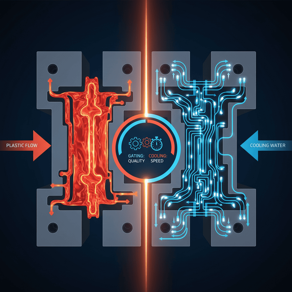
Think of it as a complete thermal management project. The gate is where hot, liquid plastic enters the mold. Its location is a strategic decision that dictates the entire filling process. At the same time, cooling channels are removing that heat. If one area cools much faster than another, the part will warp as it shrinks unevenly. For complex shapes, simple, straight-drilled cooling lines are not good enough. They create hot and cold spots, which are a primary cause of defects. The solution is to make the systems work together. I once worked on a large, thin cosmetic case that kept warping no matter what we did. The problem was that the plastic had to travel a long way from a single gate, cooling too much by the time it reached the far end. We solved it by switching to a multi-point gate system and adding conformal cooling lines that followed the part's contours perfectly. This balanced the filling and cooling, finally giving us a flat, stable part.
An Integrated Engineering Approach
-
Strategic Gate Location: The gate's job is to guide the plastic to fill the mold cavity smoothly and evenly. For a long or wide part, a single gate is often a bad idea because it creates very long flow paths. This can cause the plastic to cool down too much before the mold is full. We often use multiple gates to balance the flow, but this creates weld lines where the flows meet. Our job is to place the gates so these weld lines appear in non-critical, low-stress areas of the part. We use mold flow analysis to simulate the filling process and verify our gate strategy before cutting any steel.
-
High-Efficiency Cooling: For a complex mold, standard cooling channels are inefficient. The core and cavity are often made of many small, intricate pieces, making it hard to drill straight lines close to the molding surface. We use a technique called conformal cooling. Instead of straight lines, the cooling channels follow the exact 3D contours of the plastic part, like rivers in a valley. This provides extremely uniform and efficient heat exchange. It drastically reduces the cooling time needed for each cycle and is the single most effective weapon against warping and sink marks caused by uneven temperatures.
What's the right way to choose materials and structure for a complex mold?
A complex mold has many moving parts and faces high stress during production. Choosing the cheapest materials or a weak structure is a recipe for disaster. The mold will wear out quickly and break down.
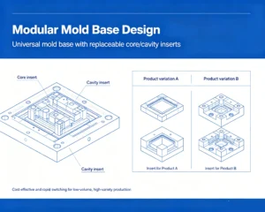
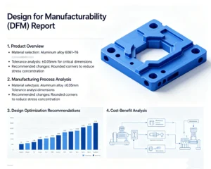
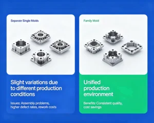
You must design for long-term stability and durability. Use a rigid mold base, high-quality tool steels, and a modular "insert" design. This ensures the mold can withstand millions of cycles while maintaining precision.
Building a complex mold is an investment in a long-term production asset. It's not about minimizing the initial cost; it's about maximizing its lifespan and reliability. A complex mold for, say, a toy with interlocking gears, involves dozens of precision moving parts like sliders and lifters. These parts slide against each other thousands of times a day under immense pressure and heat. If the mold base flexes or the steel wears down, the precision is lost. This leads to parts that don't fit together, increased maintenance downtime, and ultimately, a failed project. We build our molds for a "long war," not a single battle. This means starting with a foundation of high rigidity and selecting materials specifically for the job each component has to do.
Building for a Long Life Cycle
-
A Foundation of Rigidity: The mold base is the skeleton that holds everything together. It must be strong enough to resist flexing under the massive clamping force of the injection molding machine. Any flex, even a tiny one, will allow plastic to seep out, creating flash and ruining part accuracy. We use high-quality, pre-hardened steel for our mold bases and ensure there are enough support pillars to keep the cavity and core perfectly aligned, cycle after cycle.
-
Thinking in "Inserts": For very complex or high-wear areas, we don't machine the feature directly into the main mold block. Instead, we create a separate piece, called an insert, and fit it into the block. This has several advantages. We can make the insert from a special, more durable steel (like S136 for high-polish surfaces or a beryllium-copper alloy for better cooling). It's also easier to machine and polish a small, separate insert to a high standard. Most importantly, if that area ever wears out or gets damaged, we only need to replace the small, inexpensive insert, not the entire multi-thousand-dollar mold block.
-
Matching Steel to the Task: Not all tool steels are the same. We choose the steel based on the type of plastic being molded and the expected production volume. If the plastic contains glass fibers, it's very abrasive, so we need a very hard, wear-resistant steel. We also apply surface treatments like nitriding to critical moving parts like sliders and lifters. This creates an ultra-hard outer skin that dramatically increases their lifespan and resistance to corrosion, ensuring the mold runs smoothly for years to come.
Conclusion
Designing a successful mold for a complex part comes down to a systematic approach: smart parting surfaces, intelligent demolding, integrated thermal management, and a robust structure. This is our blueprint for quality.
Understanding parting surface design is crucial for achieving high-quality plastic parts without visible seams. ↩
An intelligent demolding system prevents damage and ensures smooth ejection of complex parts from molds. ↩
Proper integration of gating and cooling systems is essential for preventing defects and ensuring efficient production. ↩
Preventing flash is essential for maintaining part quality and reducing post-production cleanup. ↩
Ejector pins are critical for safely removing parts from molds without causing damage. ↩
Mold flow simulation helps predict filling patterns and optimize gate placement for better results. ↩